Обзор
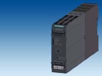 Обзор 3RM13 motor starter with reversing functionality, electronic overload protection and safety-related shutdown SIRIUS 3RM1 motor starters are compact devices 22.5 mm wide, combining a large number of functions in a single enclosure. They consist of combinations of relay contacts, power semiconductors (hybrid technology), and a solid-state overload relay for switching induction motors up to 3 kW (at 400 V) and resistive loads up to 10 A (at AC voltages to 500 V) under normal operating conditions.
The 3RM1 motor starters with overload protection with wide setting range are offered as direct-on-line starters and reversing starters and as versions with safety-related shutdown. The 3RM1 motor starters are available in four versions:
✓ Function available -- Function not available Hybrid technologyThe 3RM1s combine the benefits of semiconductor technology and relay technology. This combination is also known as hybrid technology. The hybrid technology in the motor starter is characterized by the following features:
Functional density/space requirementThe 3RM1 motor starters combine the functions of direct-on-line/reversing starting, electronic overload protection and safety-related shutdown in a single device, without changing in size. For simple applications (such as starting and reversing three-phase loads with overload protection), motor starter combinations of power contactors and a solid-state overload relay, for example, can be replaced by a 3RM1 device. The more functions are required, the more devices can be replaced. The surface area required for each motor starter in the control cabinet is reduced by values of 20 to 80 %. In the case of assemblies and grouped feeder units there are further advantages. Wiring outlayBy combining various functions in a single device, wiring outlay is reduced. The greater the scope of functions, the greater the saving in wiring. Savings can be made in:
These savings reduce the time required for the wiring itself. At the same time, they reduce both the risk of wiring errors and the amount of testing required after control cabinets have been completed. Configuration and stock keepingThe wide setting range of the electronic overload release (up to 1:5) reduces the cost of keeping stocks and the considerations involved in configuration where the actual motor current to be expected is concerned. Compared with protection equipment with thermal overload protection, only 3 versions are now required, instead of 17, to cover a current range of 0.1 to 7 A when using the 3RM1. Connection methodsThe 3RM1 is available with screw terminals and spring-type terminals or mixed connection method (screw terminals for the main circuit and push-in terminals for the control circuit).  Screw terminal for removable terminal (3-pole) for 3RM1 motor starters and 3SK1 safety relays  Spring-type terminal as push-in connection for removable terminal (3-pole) for 3RM1 motor starters and 3SK1 safety relays Push-in connection method Push-in connections are a form of spring-type connection allowing fast wiring without tools for rigid conductors or conductors equipped with end sleeves. Fine-stranded or stranded conductors with no end finishing are wired using a screwdriver (with a 3.0 x 0.5 mm blade). As with other spring-type terminals, a screwdriver is also required to release the conductor. The same tool as above can be used for this purpose. The advantages of the push-in terminals are found, as with all spring-type terminals, in speed of assembly and disassembly and vibration-proof connection. There is no need for the checking and tightening required with screw terminals. Innovative enclosure concept1 Terminals The terminals are easy to replace, optionally with screw or spring-type connections:
2 Labeled cover caps To access the top and bottom terminals, the covers must be opened. To facilitate orientation, there is a laser inscription on the inside of the caps for the connections. 3 Sealable cover To protect against unauthorized access, a sealable cover can be attached. 4 LED status display You can see at a glance from the LED status display whether operation is normal or whether faults exist. This allows fast, selective commissioning. Faults can be quickly traced and even more quickly corrected. 5 Rotary coding switch The current of the motor to be monitored can be set using the rotary coding switch. When a motor is replaced, it can be adapted within the respective wide setting range. This means that in most cases the motor starter does not have to be replaced. 6 TEST/RESET button Acknowledgment in the event of a fault: 7 Data matrix code The data matrix code enables simple and fast scanning in of article numbers and serial numbers. 8 Width The width of only 22.5 mm saves space in the control cabinet, and is thus cost-effective, especially in plants with a large number of small motors up to 3 kW.  Innovative enclosure concept for the SIRIUS 3RM1 motor starters Safety-related shutdown/safety integrationThanks to the redundant design of the main circuit and internal monitoring, safety-related shutdown in accordance with SIL 3 / PL e is possible by shutting down the control supply voltage with 3RM11 Failsafe and 3RM13 Failsafe motor starters, or in the case of the 24 V DC control voltage version, by shutting down the control inputs. Additional safety relays are not required in the main circuit.  Combination of four SIRIUS 3RM1 Failsafe motor starters with SIRIUS 3SK1 safety relay to allow safety-related collective disconnection of connected motors 3RM1 motor starters are ideal for combining with the 3SK1 safety relay (see "Safety Technology" > "SIRIUS 3SK1 Safety Relays"). They can be combined by means of:
This makes it very simple to shut down connected motors collectively. The wiring, and ultimately the shutting down of the control supply voltage in Emergency-Stop situations, is performed via the device connector. There is no further need for complex looping of the connecting cables. Feedback to the control systemThe electronic output in the 24 V DC control voltage version of the 3RM10 and 3RM12 motor starters allows the status of the connected motor to be reported to the higher-level control system. If the motor starter is controlled via inputs IN1 to 2, once the motor has been switched on and has started up correctly the output "OUT" is set. Infeed system for the main circuitThe 3RM19 infeed system available as an accessory for the main circuit with three-phase busbars allows fast, virtually error-free wiring of motor starters on the mains connection side and may reduce the number of short-circuit protective devices. Article No. scheme
1) Mixed connection method: Control circuit realized as push-in spring-type terminal and main circuit as screw terminal Область применения3RM1 motor starters are designed for applications in which small motors have to be connected in the most confined spaces. Main areas of use
Standards and approvalsThe motor starter complies with the following standards:
Тех. данные
|
||||||||||||||||||||||||||||||||||||||||||||||||||||||||||||||||||||||||||||||||||||||||||||||||||||||||||||||||||||||||||||||||||||||||||||||||||||||||||||||||||||||||||||||||


тел./факс: 8 (495) 229-56-79